Hey, I’m Krish. ✳

Freshman studying mechanical engineering at UGA.

I’m curious by nature and learn by building. This is where I share my engineering projects, from CAD models and simulations to the decisions behind them.

ENGINEERING PORTFOLIO3 PROJECTS
DESIGN / ANALYZE / ITERATE

CAD. Analysis. Iteration.

CurrentlyDesigning parts for UGA FSAE Motorsports.

Engineering portfolio.

Projects shown with the reasoning, the numbers, and what still needs proving.

01 / FSAE Motorsports · UGA

Intake Mounting System

Holding a 3D-printed intake still on a race car.

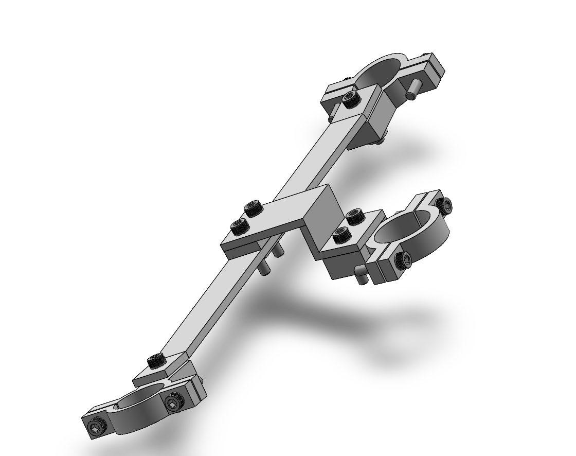
A bracket system that supports the car’s existing intake in its fixed position, stops unwanted movement, and keeps vibration and weight down. I covered it from rules and concepts through CAD, simulation, a manufacturing plan, and a costed budget.
CADFEADFMBudgeting
CAD render of the intake mounting assembly: three split clamps joined by a steel crossbar and connector bracket
Assembly CAD · clamps, crossbar, connector
3Split clamps in 6061-T651 aluminum
138.5 MPaPeak simulated stress at 600 N (≈ 60 kg)
$367Planning budget for a team-shop build (incl. 20% contingency)

01 · The problem

Support the intake without damaging it.

The intake is 3D-printed and has to stay exactly where it is. The FSAE rules set the constraints. Supports attached to the engine must be rigid. Supports attached to the chassis need some isolation for engine movement. Threaded fasteners need positive locking, so a loose fastener can’t fall out.

I also wanted to keep the mount light and leave the sensors, bolts and intake removal easy to get to.

02 · Concepts

Two ideas, one feasible.

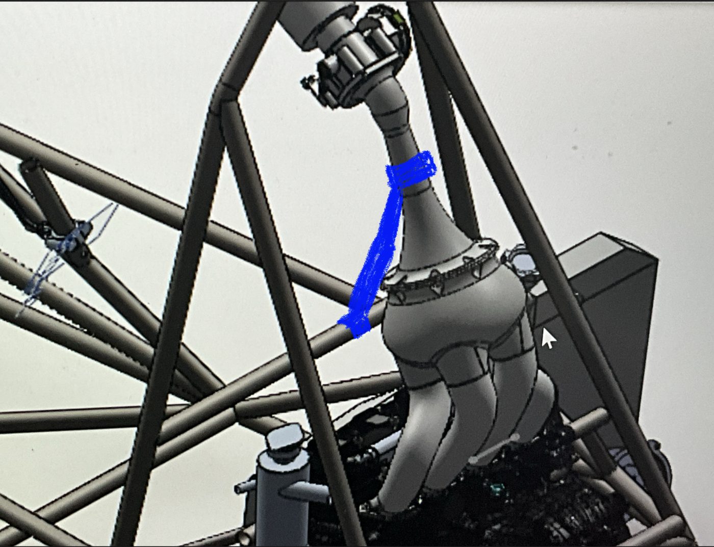
Concept 1 clamps the intake neck with a split collar and ties it to two chassis tubes through a crossbar. Concept 2 needed a second mounting point. When I checked it against the CAD model, that point was too far away to be practical, so I developed Concept 1.

The risk with Concept 1 was that a tight clamp could crush the printed intake. To prevent that, I added a nitrile rubber liner between the collar and the intake.
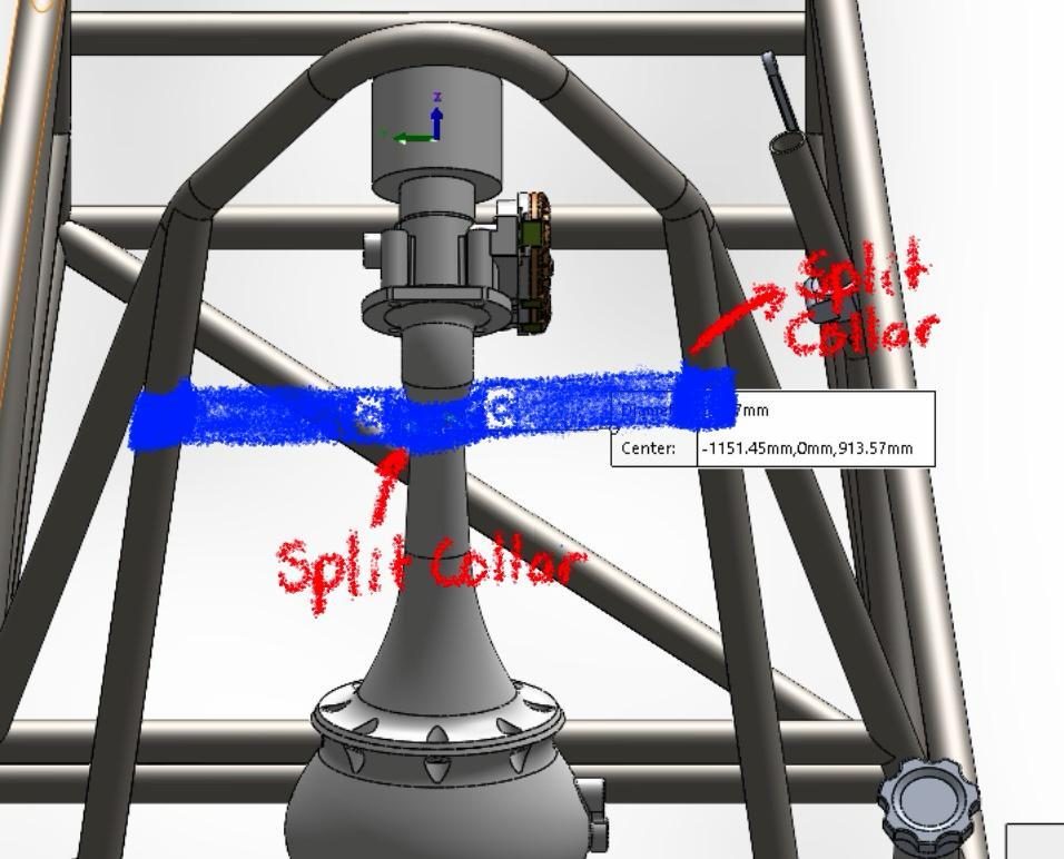
Concept 1 sketch: split collars on the intake neck and a crossbar to the chassis
Concept 1 · split collar + crossbar
Concept 2 sketch: a diagonal brace from intake to frame
Concept 2 · rejected, mount point too far

03 · Design

Aluminum where it’s machined, steel where it’s welded.

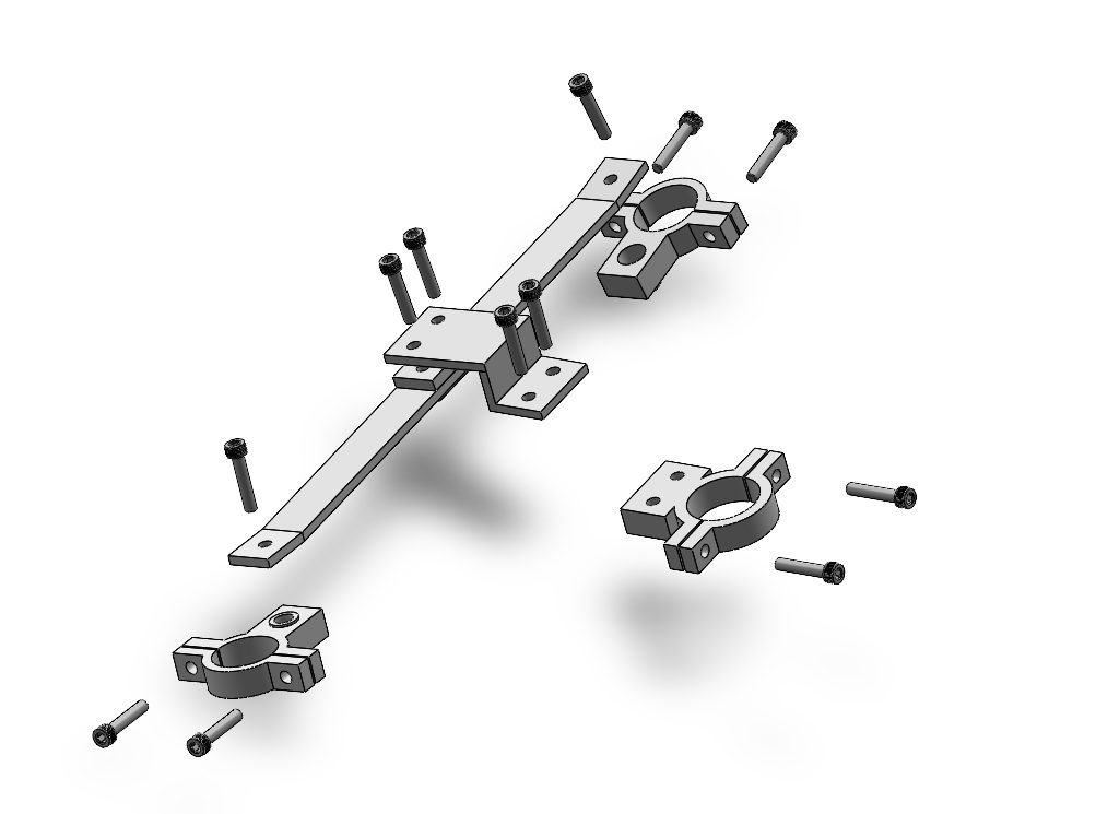
The clamps are machined from 6061-T651 aluminum because it’s lighter than steel and easy to machine into split collars with built-in tabs. The crossbar and connector are 1018 mild steel, cut into simple pieces and welded in a fixture instead of bent to match the lofted CAD shape. Rubber bushings at the chassis end let the engine move. Steel sleeves stop the bolts from crushing the rubber, and all-metal locking nuts meet the positive-locking rule.
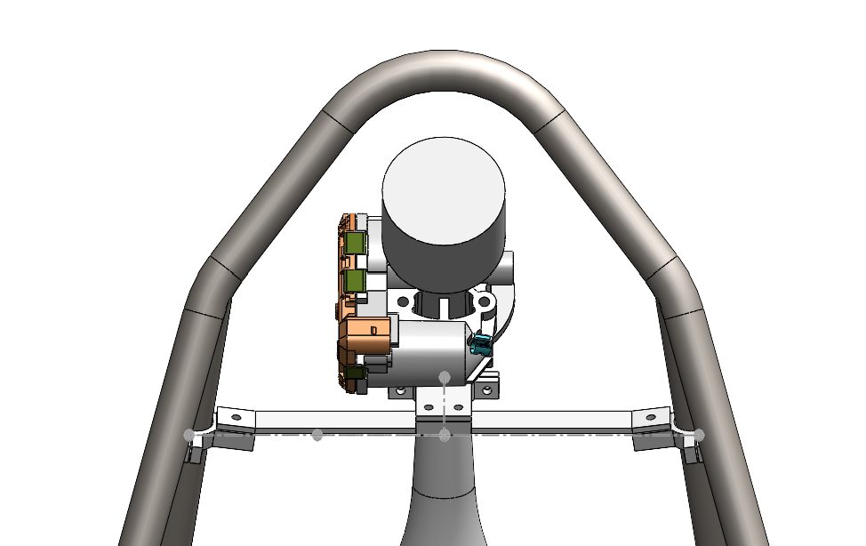
Front view of the mount installed in the chassis CAD
Installed in chassis · front
Exploded view of the mount with its bolts and clamp halves
Exploded view · fasteners

04 · Simulation

Testing it at 100 N and 600 N.

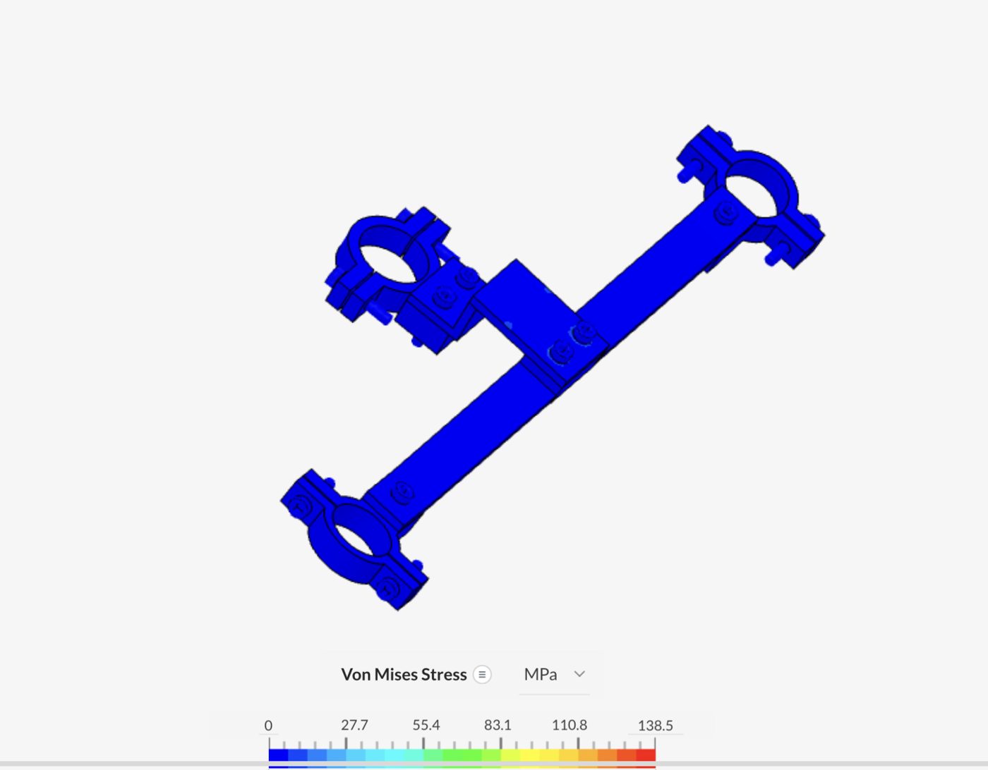
I ran static stress simulations at 100 N (about 10 kg of force) and 600 N (about 60 kg). The peak von Mises stress was 23.09 MPa at 100 N and 138.5 MPa at 600 N.
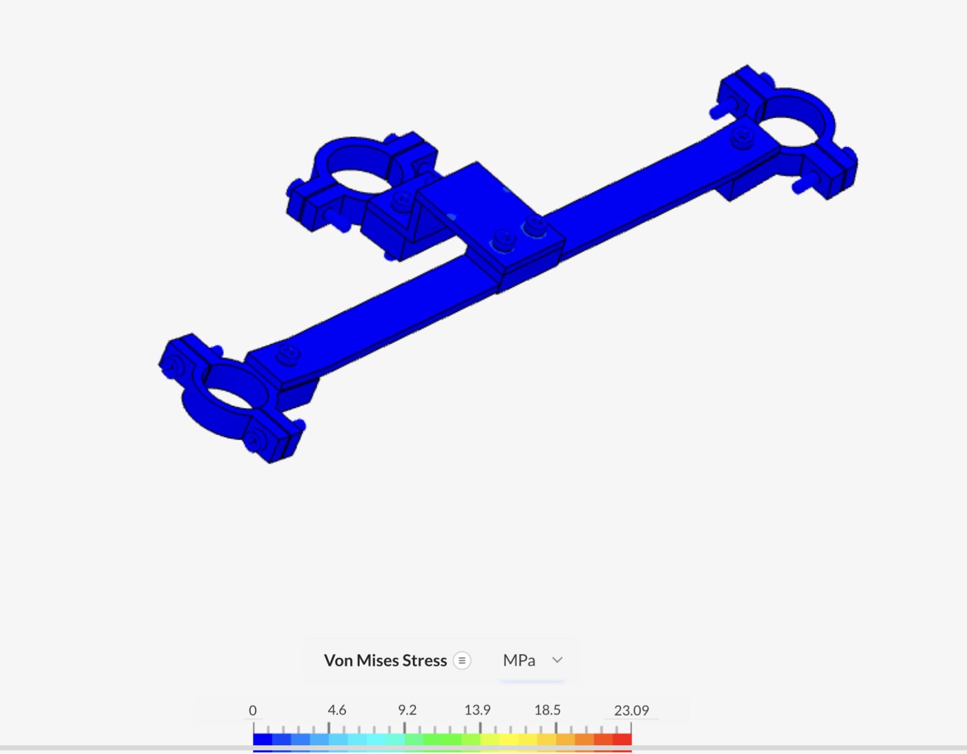
Von Mises stress plot at 100 newtons, peak 23.09 MPa
100 N · peak 23.09 MPa
Von Mises stress plot at 600 newtons, peak 138.5 MPa
600 N · peak 138.5 MPa

Next: trace where each peak sits so I can compare it with that part’s material strength. I also need to check the bushing stiffness and set a torque and compression spec, then test grip and retention on the car.

05 · Build + cost

A plan someone could actually build from.

  1. Fit rubber liners inside the aluminum clamps.
  2. Close the clamps around the chassis tubes and the intake neck at the CAD locations without moving the intake to force a fit.
  3. Insert the bushing halves and metal sleeves into each chassis lug.
  4. Bolt on the crossbar, then the connector between the intake collar and the crossbar.
  5. Check alignment, tool access and clearance, then torque to a defined spec rather than by feel.
Budget itemPaid shopTeam shop
Materials + supplies$255.66$255.66
Manufacturing (12.25 h)$762.50$0 cash
Shipping + tax$50.45$50.45
20% contingency$213.72$61.22
Total$1,282.33$367.33

Prices for stock material and hardware are listed supplier prices. Bushings, labor rates and consumables are estimates, not quotes.
02 / Personal project

HALO-12

An Earth-imaging satellite concept.

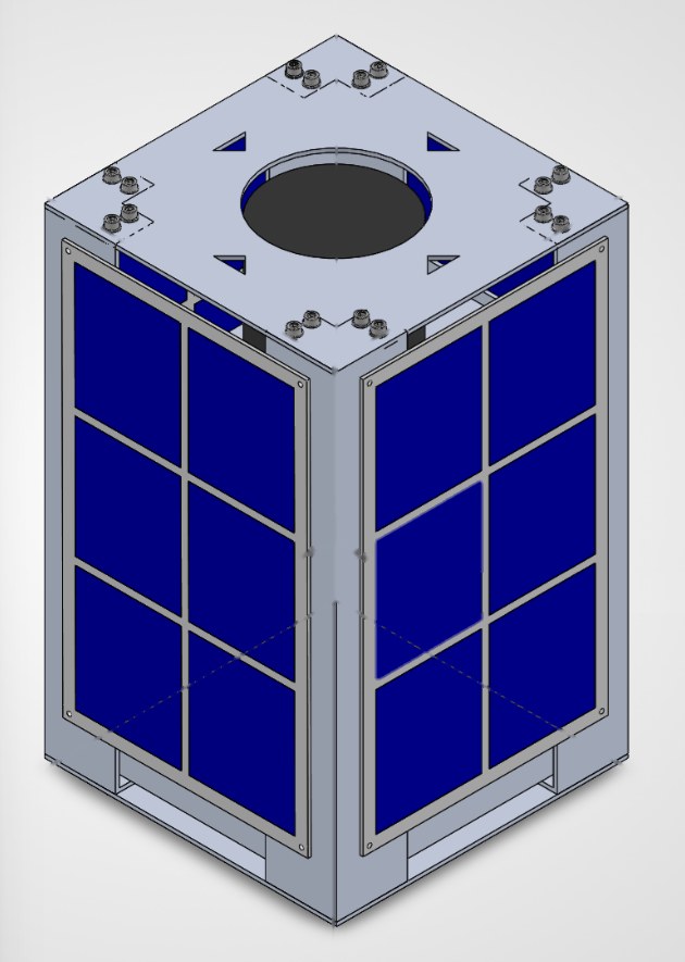
Exploring how structure, camera placement, and onboard systems fit together in a compact 12U satellite.

CADStructural analysisSatellite design
CAD render of the HALO-12 12U satellite assembly
Full assembly · CAD
12USatellite format
500 kmConcept orbit altitude
10 gAssumed structural test load

01 · How it fits

Camera, internals and panels inside one frame.

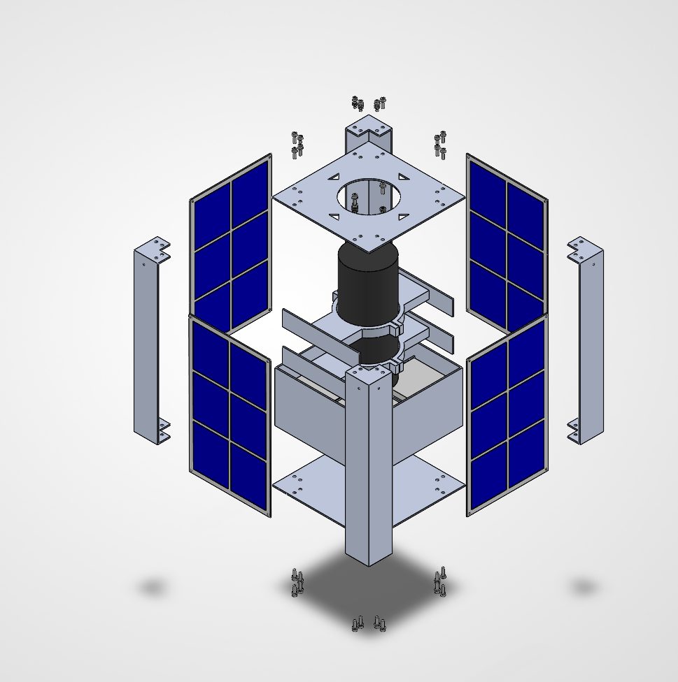
The exploded view shows the plates, rails, solar panels and how the internal equipment is packed. The design changed through part comparisons, camera-fit revisions and an initial orbital power budget.

Exploded CAD view of HALO-12 showing plates, rails, panels and camera
Exploded view

02 · The decision

The camera changed the design.

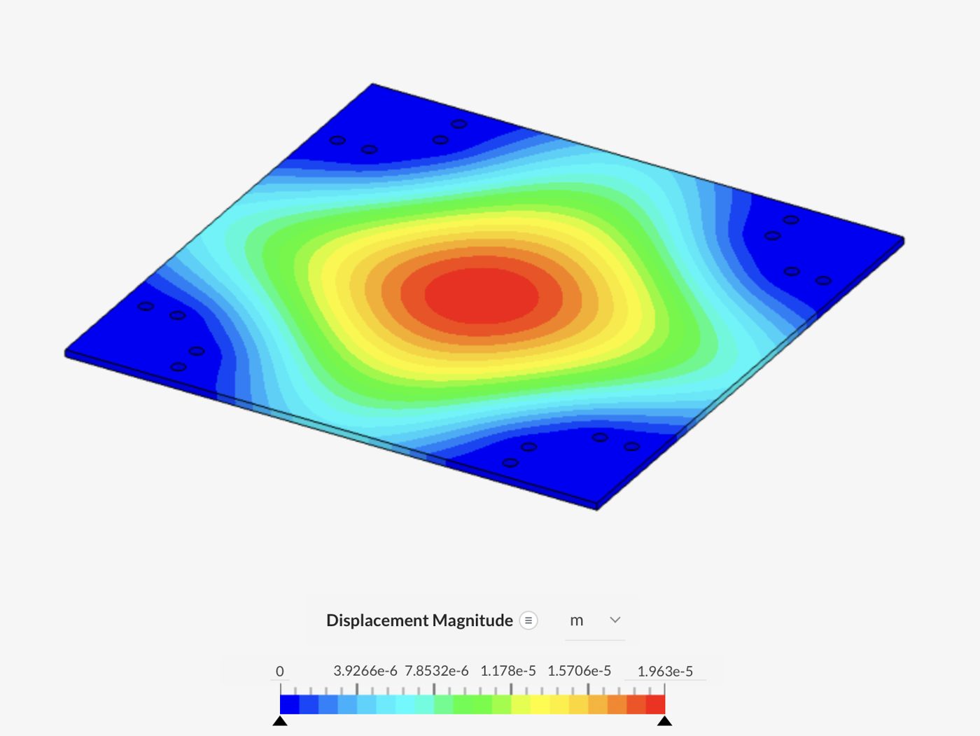
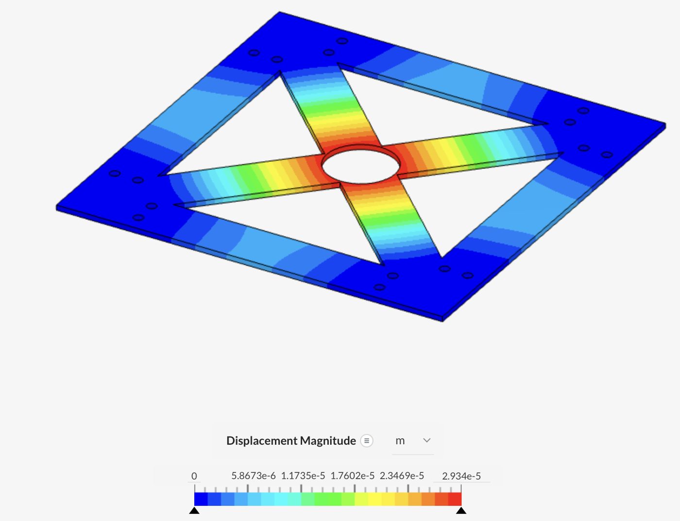
An early study compared a solid top plate with an open X-frame at an assumed 10 g. The X-frame was 134 g (32.6%) lighter but bent about 49% more. I didn’t keep it, because its 40 mm opening couldn’t fit a camera roughly 95 mm wide. I replaced it with a revised plate that has a larger opening.

Displacement plot of the solid plate
Solid plate · 411.74 g · 0.0196 mm
Displacement plot of the open X-frame
X-frame · 277.72 g · 0.0293 mm

03 · Full assembly

Static, modal and thermal.

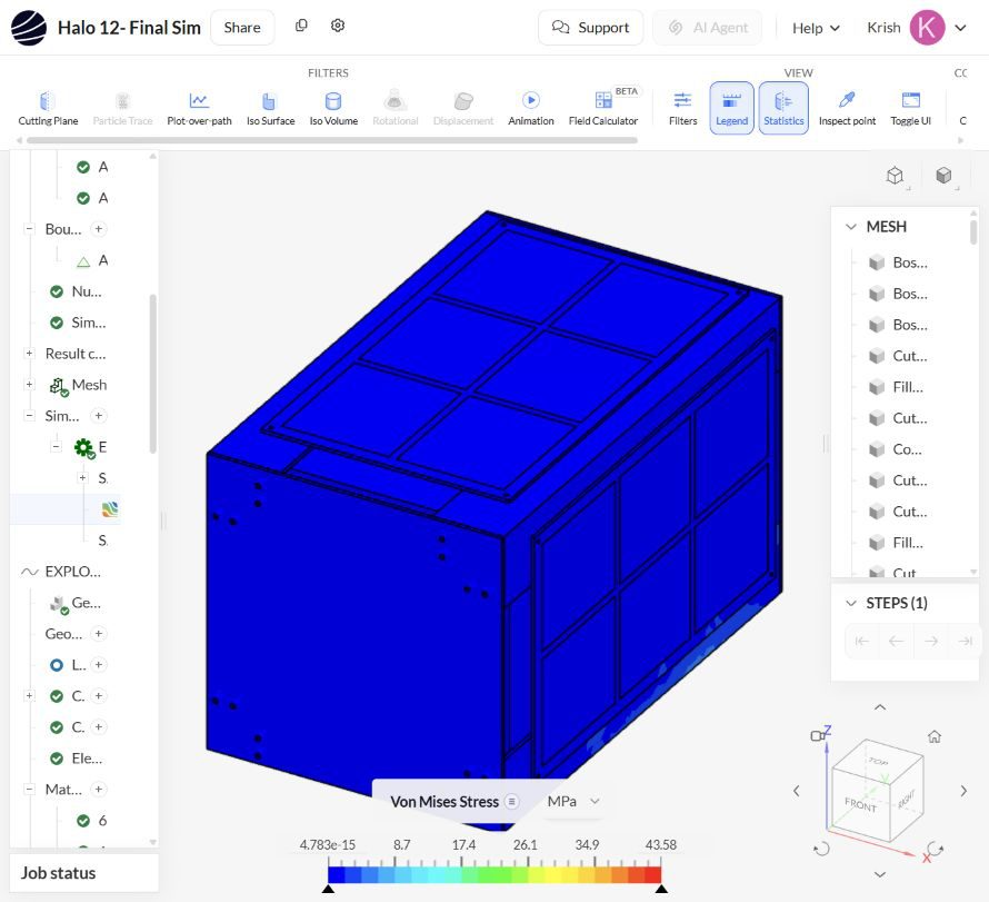
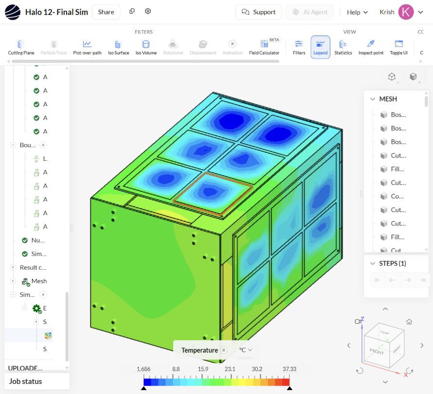
With the bottom face held fixed at 10 g, the full assembly moved at most 0.462 mm and peaked at 43.58 MPa. Ten reported natural frequencies fell between 77–580 Hz. A steady model with 30 W of internal heat gave temperatures from 1.7 °C to 37.3 °C.

Von Mises stress plot of the full satellite assembly
Stress · 43.58 MPa peak
Steady thermal plot of the satellite
Thermal · 30 W steady case

These are early simulation results, and the satellite is not flight-qualified. Next, I need to trace the stress peak to a specific part so I can work out a safety factor. I also need to refine the mesh, model the real supports, and run random-vibration and orbit-cycle thermal analyses.

03 / FSAE Motorsports · UGA

FSAE Bell Crank

COMING SOON

About me

A little about me.

I’m a freshman studying mechanical engineering at the University of Georgia and a member of FSAE Motorsports. I like projects where I have to make a real design decision and back it up with analysis.